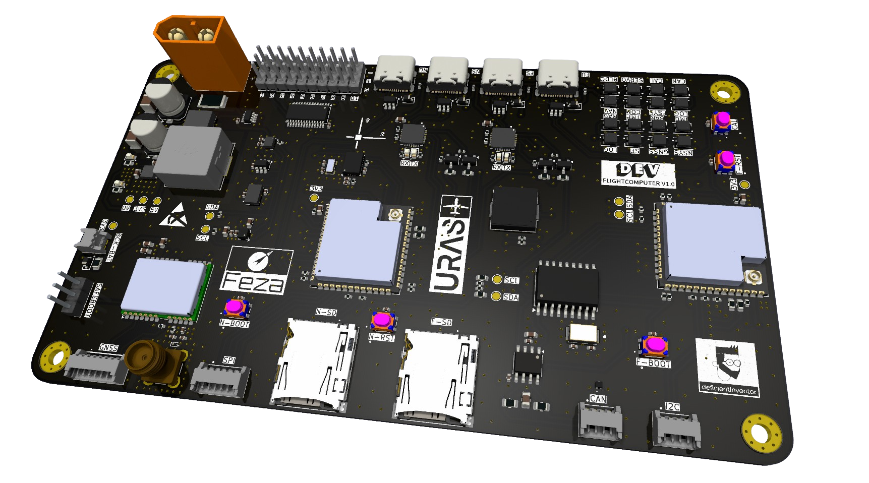
DEV Flightcomputer V1.0
a blogpost for the review.
- You can easily navigate through the contents navigation bar on the right side.
- Feel free to skip the text explanations if you prefer to directly view the design files.
Introduction
Purpose of the PCB
This PCB is designed as a primary development platform to explore a variety of exciting fields, including:
- Model rockets
- Flight computers for fixed-wing aircraft or multicopters
- Robotic control systems
It serves as a general-purpose computer with CAN bus capability, allowing it to function as the central brain for specialized, task-focused PCBs.
Background
The development of this PCB is the result of approximately three months of intensive learning, during which I studied:
- PCB design principles
- Datasheets of components
- Insights from forums such as r/PrintedCircuitBoards and r/AskElectronics
Key references include:
- The Hades flight computer by Phil’s Lab
- Peripheral designs from Reddit, Adafruit, and SparkFun
This journey has been a mix of research, experimentation, and building a deeper understanding of electronics.
Components and Software
The components were selected based on their compatibility with existing libraries for popular development platforms like:
- PlatformIO (PIO)
- ESP-IDF
- Arduino
This approach enables rapid prototyping while providing a pathway to learn bare-metal programming by studying and adapting these libraries.
Future Iterations
As a self-taught enthusiast and not a trained electrical engineer, this design represents the best I could achieve with my current knowledge. Future iterations will focus on:
- Addressing hardware limitations
- Refining the design as I gain more experience
- Implementing improvements based on real-world testing and feedback
This iterative process is key to evolving the PCB into a more robust and versatile platform.
Design Choice
Power Management
This PCB is powered by a LiPo battery in combination with a switching regulator capable of delivering 5V at up to 9 Amps. This configuration is designed to provide sufficient power to operate at least three servos, each with a stall current of 2.5–3 Amps.
Voltage Regulation, Distribution and Monitoring
- Switching Regulator Circuit: Supplies 5V at a maximum of 9 Amps to the servo headers and the VDD pin of the CAN transceivers.
- LDO (Low-Dropout Regulator): Generates 3.3V logic levels for the MCU and sensors.
- INA219 Current Sensor: Enables real-time current monitoring for enhanced power management.
Actor Power and Expansion
The number of supported servos will be determined through testing. ESCs will connect via servo headers but rely on their own LiPo battery, ensuring a stable power source for the BLDC motors. Future plans include a slave PCB with CAN bus for controlling BLDCs and servo motors, featuring integrated encoders/decoders and its own dedicated power supply circuitry.
The switching regulator circuit, based on Phil’s Lab Hades flight computer, is the most complex part of the schematic and has been replicated 1:1 from his design. Testing will guide iterative refinements to ensure reliable power management under load.
USB Interface
The USB interface is largely based on a 1:1 copy of the dev board schematics, with a few modifications to suit this PCB’s needs:
Key Modifications
- USB-C Ports: Replaced the original Micro USB ports with USB-C for improved durability and versatility.
- TX/RX Transmission LEDs: Added to the USB-UART converter for better visibility of data transfer activity.
- Auto Programmer Logic: Retained for development purposes, simplifying the programming process.
- ESD Risk Reduction: Designed with precautions to minimize electrostatic discharge (ESD) risks during handling.
Flight Computer Controller Unit (FCCU)
The Flight Computer Controller Unit (FCCU) acts as the central brain of the system, running the primary algorithms and managing key functionalities.
Features
- SD Card: Functions as a read/write eMMC for:
- Data logging
- Saving calibration data to avoid writing to the ESP’s internal EEPROM.
Current Sensor: Monitors the battery state to ensure reliable power management.
CAN Bus: Serves as an extension slot for task-specific slave PCBs, providing flexibility for future expansion.
- Buzzer: Used for feedback, such as:
- Battery state alerts
- Specific system states
- Error notifications
- Location indication (e.g., if the system lands somewhere unexpected).
- Status LEDs: Indicate key statuses, including:
- Calibration progress
- Communication activity
- Servo Headers:
- 3x10-pin 2.54mm (0.1”) servo headers capable of 5V @ 9 Amps max for:
- Six servos
- Four BLDCs with external ESCs & LiPos.
- 3x10-pin 2.54mm (0.1”) servo headers capable of 5V @ 9 Amps max for:
- I2C Molex Connector: Additional board-to-wire connection for peripherals or other components not yet specified.
The FCCU is designed to handle a wide variety of tasks while being modular and expandable, ensuring adaptability for future use cases.
Navigation Controller Unit (NAVCU)
The Navigation Controller Unit (NAVCU) acts as the dedicated brain for navigation tasks, handling computation-heavy sensor fusion and managing a wide array of peripheral sensors. It communicates with the FCCU via UART and I2C and is optimized for navigation-specific operations.
Features
- SD Card:
- Functions as a read/write eMMC for:
- Detailed data logging during development stages for analytics and error handling.
- Storing calibration data, avoiding writes to the ESP’s internal EEPROM.
- Unlike the FCCU, the NAVCU focuses on logging detailed sensor data, while the FCCU logs only mission-critical information for transmission to the ground station.
- Functions as a read/write eMMC for:
- CAL_BTN:
- A calibration button for manual sensor calibration when needed.
- SPI Molex Connector:
- Includes an extra board-to-wire connection for SPI.
- Can also function as four GPIO pins due to the pin multiplexing capabilities of the ESP32S3.
- GNSS Module:
- NEO-M9N with a dedicated board-to-wire Molex connector for configuration via an external USB-to-TTL adapter.
- IMUs:
- BNO055 (9DoF): Primary IMU for accurate sensor fusion.
- BMI088 (6DoF): Redundant secondary IMU for backup.
- Magnetometer:
- IIS2MDCTR (3DoF): Complementary to the BMI088, enhancing accuracy in navigation tasks.
- Temperature Sensor:
- TMP100: Monitors board temperature to identify and address potential heat absorption issues.
- Barometer:
- DPS310: Barometric pressure sensor for precise altitude measurements.
The NAVCU is specifically designed to offload navigation tasks from the FCCU, enabling efficient and precise control over flight dynamics while maintaining flexibility for future enhancements.
Uncertainties
There are four key areas where I have some uncertainties regarding the current PCB design:
1. Schottky Diodes
- Placement: I’ve placed a total of six Schottky diodes, one for each power source:
- 4x USB
- 1x Switching Regulator
- 1x Hot-Start GNSS External Battery Connector
- Concern: Are these placements correct, and have I missed any necessary Schottky diodes?
2. ESD Protection
- Current Placement:
- 2x ESD diodes on each SD card slot.
- 4x ESD arrays for each USB slot.
- 1x ESD diode on the GNSS SMA antenna.
- 1x ESD diode on the CAN bus Molex connector.
- Missing ESD Protection:
- I²C external connector
- External SPI Molex connector
- Boot, reset, and calibration buttons
- Safeboot header for the GNSS module
- Molex connector of the GNSS module
- Hot-start battery connector for the GNSS module
3. Test Points
- Concern: While I believe the current test points are sufficient, I am still uncertain and would appreciate feedback.
4. F.Mask for the BMI088
- Issue: There’s uncertainty about the F.Mask configuration for the BMI088 and whether it good or bad for manufacturing.
These uncertainties highlight areas where I may need further review or guidance to ensure the design is robust and functional.
Schematic
- You can access the PDF via the attached link or the PDF viewer.
Schematic Colored
Schematic Monochromatic
Trace’s / Impedance / Board
Power
| TraceID | TraceWidth (mm) |
|---|---|
| VBAT | 2.5 |
| +5V | 0.5-2.5 |
| +3V3 | 0.5 |
| REG_FB | 0.35 |
| GND | 0.5-4 |
Signal
| TraceID | TraceWidth (mm) | Spacing (mm) | Impedance (Ω) |
|---|---|---|---|
| RF / SPI | 0.327 | 0.6 | 50 |
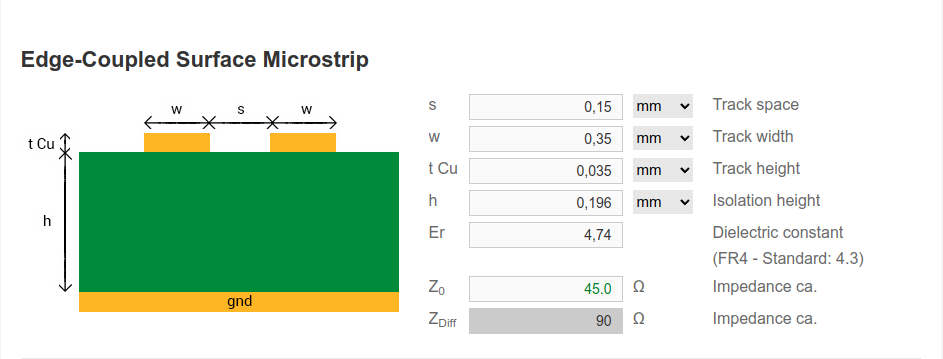
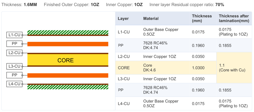
| USB | 0.35 | 0.15 | 90 |
| UART | 0.327 | 0.6 | 50 |
| I2C | 0.327 | 0.6 | 50 |
| SIGNAL | 0.327 | 0.6 | 50 |
Calculations
50 Ω
90 Ω
Board
| Boardfinish | ENIG |
| Tented Vias | YES |
Gerbers as SVGs / ZIP
- For better visibility, open the SVGs in a new tab by right-clicking and selecting Open pic in new tab.
Layer 1 (SIG)
Layer 2 (GND)
Layer 3 (PWR)
Layer 4 (SIG)
F-MASK
- I included the Front Mask layer due to uncertainty about the BMI088 masking. It’s the first IC to the left of the test point on the middle ESP32 (NAVCU). I’m unsure if a correction is possible.
- If you can’t locate the BMI088, use the interactive BoM and filter to find its exact position.
Gerber Viewer & Download
- To use tracespace.io, click the settings wheel and set the use outline layer for board shape GAP FILL LIMIT to 0.25mm for an error-free board view.
Fabrication Document
Assembly Document
Bill of Material
Interactive BOM
- In case you prefer to use the fullscreen iBoM, you can acces it via the Settings Gear.
Costs
| Item | Price |
|---|---|
| Components | 147,74€ |
| PCB Manufacturing | 106,51€ |
| PCB Assembly | 29€ |
| TOTAL | 283,25€ |
 pie
    title Cost Breakdown
    "Components: 147,74€" : 147.74
    "PCB (5): 106,51€" : 106.51
    "Assembly (1): 29€" : 29
Reports
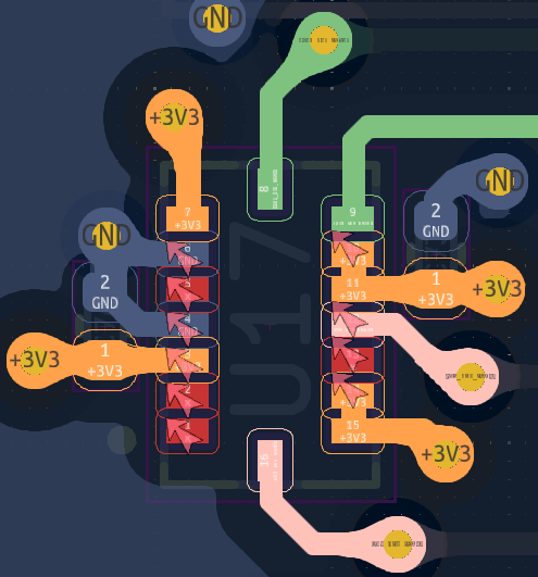
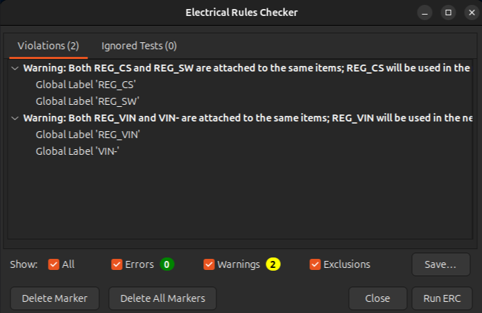
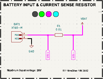
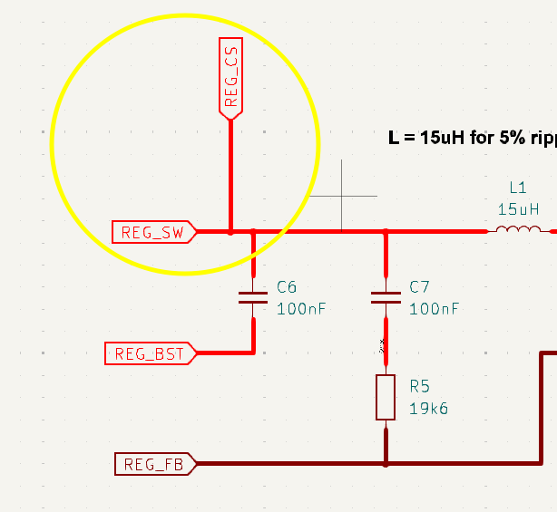
- The warnings from the electrical rule checker are known and occur due to the INA219 Current Sensor, its current sense resistor, and the schematic of the switching regulator. Schematic snippets are attached for inspection.
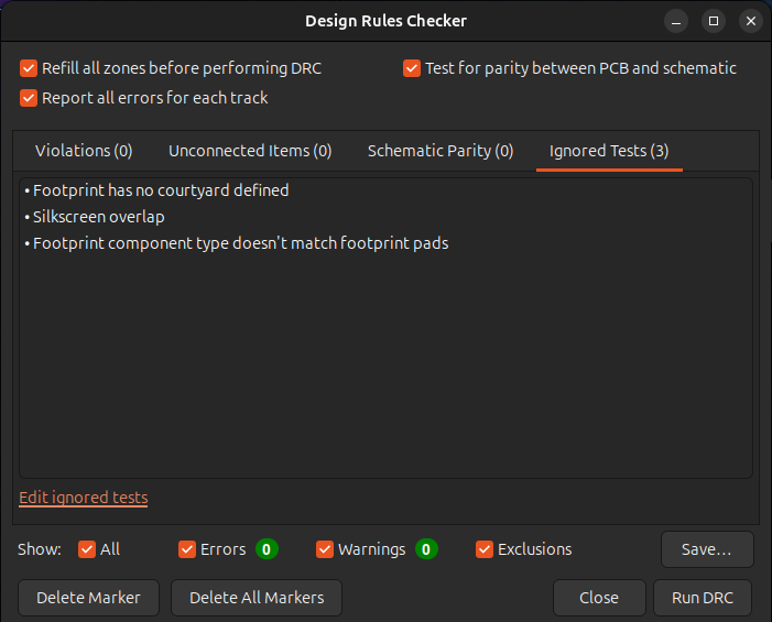
- The ignored test “Footprint component type doesn’t match footprint pads” in the DRC is due to the USB connectors, as they are both SMD and THT.
ERC
VBAT goes into REG_VIN
DRC
- 0 Errors if -> /File/Board Setup/Board Stackup/SolderMask&Paste/Allow bidged solder mask apertures between pads withing footprints
Known Issues
- Soldermask BMI088 (unsure, not enough knowledge)
- TBD
Thank you for joining me on this journey! Feedback and suggestions are always welcome as I continue to improve and learn.
Credits
- KiCad EDA
- Tracespace Online Gerber Viewer
- SVGCrop
- Phil Salmony - PhilsLab Hades (Project Inspiration)
- Vincent Nguyen (KiCad Documentation Inspiration)
- LiveLeds (Github-Pages Documentation Inspiration)
- r/PrintedCircuitBoards
- r/AskElectronics
